Boost Converter Inductor Selection
Design and selection of the boost inductor Design and selection of the input capacitors To be clear the other common use of the boost converter is for AC to DC power supplies for power factor correction and that requires a complete and separate treatment. Boost inductor cricuit Figure 3 is a typical Boost converter circuit.
Laying Out An Inverting Buck Boost Converter For Success Power Management Technical Articles Ti E2e Support Forums
Traditionally the inductor value of a boost converter is selected through the inductor current ripple.

Boost converter inductor selection. Ive increased the inductor size to reduce its current ripple but the best option is to select a low ESR capacitor. This is given as. Different core materials have different properties.
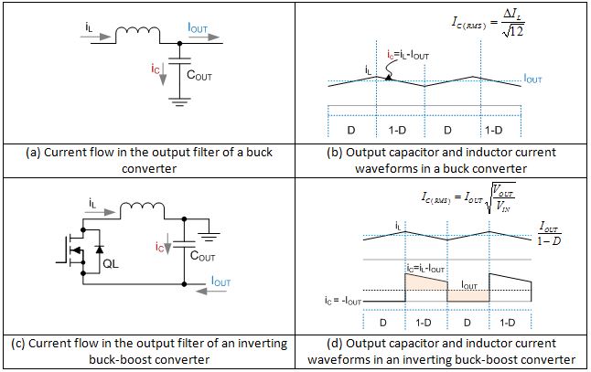
INDUCTOR SELECTION Once the proper boost regulator is selected the next step is to calculate the inductor value which can be done with Equation 3. There are two groups of DC-DC converter topologies that should be considered here. The boost converter has the filter inductor on the input side which provides a smooth continuous input current waveform as opposed to the discontinuous input current of the buck or buck-boost topology.
Higher inductance leads to lower ripple current which leads to lower ripple voltage through ESR of output cap. There is also core material although this applies moreso to winding your own. Inductor Selection in Boost Converters for LCD Backlight Applications 1 The inductors RMS current IL_RMS is the effective current which leads to most of the inductors self heating.
In this TI App note under Inductor Selection on page 3 it is asking to assume the inductor ripple current as a percentage of OUTPUT CURRENT. Maximum input voltage Output voltage Switching frequency Maximum ripple current Duty cycle Inductor selection. Ive a question regarding the inductor selection in a boost converter.
The input voltage of this converter is always smaller than the output voltage. This is a general circuit of a boost converter below In the above circuit we can see the inductor is connected to the input voltage. The boost converter works in the following way.
Boost converters will step-up the input voltage to a higher output voltage. LTC3783 OPERATION Boost Converter. Boost inductor Inductor selection.
Boost Inductor Diode Input Voltage 5V Switch Output Cap 12V Output Voltage Figure 3. 3 D is the boost duty cycle in continuous conduction mode given as. The boost converter works in the following way.
The current flows through inductor L1 and the S1 when S1 is closed charging L1 but no power will deliver. BuckboostCuksplit-Pi converters and resonant bridge converters. 2 IL is the inductor peak to peak current ripple given as.
This is accomplished by charging an inductor via an internal MOSFET switch and discharging the inductor via a rectifier to the load when the MOSFET switch is off. Buck Boost and Cuk Converter Inductor Selection. Boost Converter MC13783 Buck and Boost Inductor Sizing Application Note Rev.
Inductor selection is based on a few things. This article walks both the experienced power conversion specialist and nonspecialist through the inductor catalog and the important specifications. 3 Where L is the inductor inductance V in is the input voltage V out is the output voltage I L is the inductor.
01 Freescale Semiconductor 5 The operating frequency and inductor selection are inter-relate d in that higher operat ing frequencies allow the use of smaller inductor value. This article will discuss how to choose a proper inductor using step-up DC-DC known as Boost Converter A simplified boost converter circuit can be seen in Figure 1. The average input current I LDC_MAX of the inductor is calculated using Equation 1.
Proper inductor selection requires a good understanding of inductor performance and of how desired in-circuit performance relates to the information available in sup-plier data sheets. Buck converters Figure 3. When selecting an inductor for a buck converter as with all switching regulators youll need to define or calculate the following parameters.
However operating at a higher frequency generally results in lower. The input voltage of this converter is always smaller than the output voltage. Inductor selection for Boost converters The Boost converter uses the same procedure as the Buck con-verter with a modification of the formulas for duty cycle and inductor voltage change.
The operating frequency and ripple current in the inductor the inductor value can be determined using the following OUTPUT equation. This article will discuss how to choose a proper inductor using step-up DC-DC known as Boost Converter A simplified boost converter circuit can be seen in Figure 1. Inductor selection for switching regulators Technical Note 4031 Effective December 2017 The following parameters need to be defined or calculated to select an inductor.
VOLTAGE 200mVDIV V L INMIN. The current flows through inductor L1 and the S1 when S1 is closed charging L1 but no power will deliver. Buck boost and buck-boost converter topologies as well as the related Cuk and split-Pi converters all make use of an inductor to store energy when the power MOSFET in the.
Inductor Selection been shown to contribute significantly to EMI. Any attempt Given an operating input voltage range and having chosen to damp it with a snubber will degrade the efficiency. Ceramic capacitors have such a low ESR they are essentially considered to have none and for this reason have become a favourite in DC-DC converter designs.
Boost converters are used when V OUT needs to be higher than V IN.

The Dc Dc Boost Converter Power Supply Design Tutorial Section 5 1 Power Electronics News
Two Boost Converters With Interleaving Inductor Currents In Dcm Download Scientific Diagram

Boost Converter And Its Steady State Waveforms A Boost Converter B Download Scientific Diagram

How To Select The Right Boost Regulator Ics For Modern Day Circuit Designs Tps610992 By Texas Instruments In 2021 Circuit Design Function Generator Inductors

The Dc Dc Boost Converter Power Supply Design Tutorial Section 5 1 Power Electronics News

The Dc Dc Boost Converter Power Supply Design Tutorial Section 5 1 Power Electronics News

How To Select The Right Boost Regulator Ics For Modern Day Circuit Designs Basics Of Boost Converter In 2021 Circuit Design Function Generator Circuit

A Traditional Buck Boost Converter B Continuous Input Current Download Scientific Diagram

The Calculator Diy Dc Dc Boost Calculator Adafruit Learning System

An Introduction To Buck Boost And Buck Boost Converters Recom

The Dc Dc Boost Converter Power Supply Design Tutorial Section 5 1 Power Electronics News

An Introduction To Buck Boost And Buck Boost Converters Recom
Parameter Comparison Of Boost Cascaded Boost Converter For 100 W Download Table

Proposed Zvs Boost Converter Topology Download Scientific Diagram
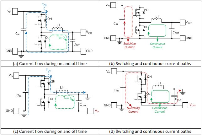
Laying Out An Inverting Buck Boost Converter For Success Power Management Technical Articles Ti E2e Support Forums

Current Waveforms Of Boost Converters A Inductor Current Waveform Download Scientific Diagram
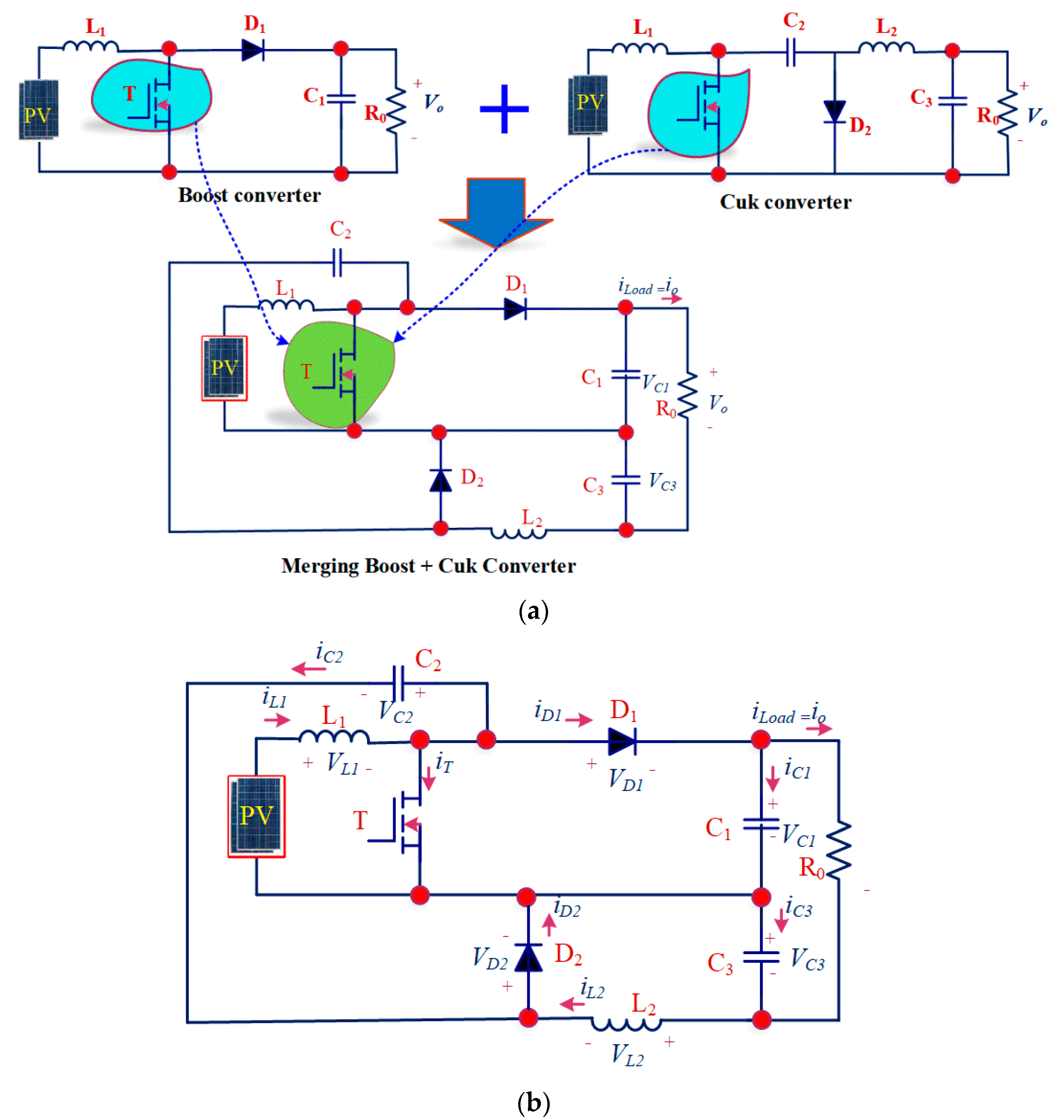
Energies Free Full Text A Hybridization Of Cuk And Boost Converter Using Single Switch With Higher Voltage Gain Compatibility Html

A Topology Of H Bridge For The Buck Boost Converter And B Energy Download Scientific Diagram

Boost Converter Systemmodeler Model
Post a Comment for "Boost Converter Inductor Selection"